Web Services Translation Tool
WST
| Home | ||
| About | ||
| Documentation | ||
| Download | ||
| Web Help | ||
| Bugs | ||
| Contact | ||
 Version 1.0
Index
Introduction
RT-UML editor
Sequence Diagram Simulator
RT-UML2WS-CDL
WS-CDL2TimedAutomata
WS-CDL2CPNTools
Example: An Aero-electric Management System (AMS)
Example: A Form Generator Service (FGS)
Example: An Internet Purchase Process (IPP)
Example: Registered Voters Management (RVM)
Example: An Aero-electric Management System (AMScpn)
Example: An Airline Ticket Reservation System (ATRScpn)
Introduction
Web Services Translation Tool (WST) is an integrated environment for translating XMI documents corresponding to UML 2.0 sequence diagrams into WS-CDL specification and WS-CDL specifications into Timed Automata supported by UPPAAL tool or coloured Petri nets supported by CPNTools.
WST applies several XSL Stylesheets to an initial XML document to obtain a new XML document. For instance, four XSL Stylesheets are used in order to translate an initial WS-CDL document into another XML document representing the Timed Automata system supported by UPPAAL tool.
RT-UML editor
The first tab, called "RT-UML DIAGRAM", allows the user to model a UML sequence diagram that represents the system interactions between the different parties and time restrictions. A diagram showing the different part of this diagram is shown in Figure 1.
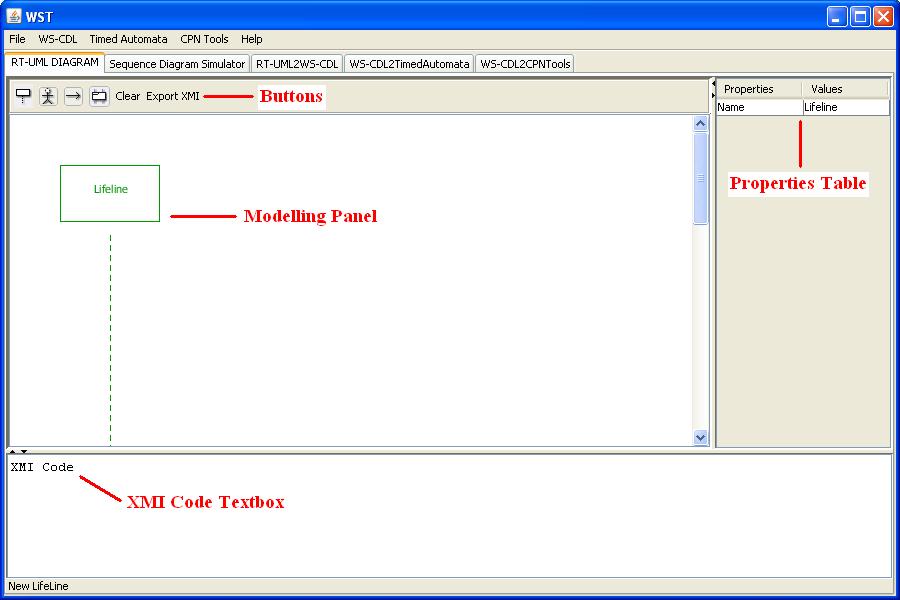
Figure 1. UML sequence diagram editor
The modelling panel has six buttons on the top, from left to right:
-
The New Lifeline button allows the user to include a new lifeline in the diagram. By left-clicking the button, the tool automatically includes the new lifeline after the actors and the lifelines included before which a default name (Lifeline, Lifeline1, Lifeline2,...).
-
The New Actor button allows the user to include a new actor in the diagram. By left-clicking the button, the tool automatically includes the new actor after the lifelines and actors included before which a default name (Actor, Actor1, Actor2,...).
-
The New Message button allows the user to create a new message interaction between two different parties. The user must left-click over the first element on the panel (actor or lifeline sender of the message) and then left-click over the second element (actor or lifeline receiver of the message). After clicking both elements the tool will display a message from the first element to the second element which a default name (Message, Message1, Message2,...). The order of the message in the diagram relative to other messages and frames added before depends on the height where the user left-click over the first element, including the message in a frame if the user left click inside the frame.
-
The New Frame button allows the user to add a new frame to the diagram. By left-clicking the button, the user can choose the type of frame to create, Alt alternative, Alt if/else, Opt optional, Loop, Par parallel or Exception. After that, the user must left-click over one actor or lifeline (it doesn't matter which one) to place the frame in the diagram. The order of the frame in the diagram relative to other messages and frames added before depends on the height where the user left-click over the diagram, including the frame in another frame if the user left click inside this other frame, except in the case of the Exception frame which is automatically place at the end of the diagram.
-
The Clear button allows the user to delete the current diagram completely and starting the design again from the beginning. By left-clicking the button, a dialog will be shown to the user to confirm the action of deleting all the components.
-
The Export XMI button allows the user to create an XMI document corresponding to the current diagram. By left-clicking the button, a dialog will be shown to the user to select the name and the place of this document in the operating system. Once the code has been saved, it will be displayed also in the XMI Code part of the tab.
The different types of frames that can be chosen have the following meanings:
-
Alt alternative: This frame is divided into different parts (from 2 to n) which meaning is that only one of this parts if executed but we don't now which one (we don't have any way to now which part will be choose).
-
Alt if/else: This frame is divided into two parts, the if part and the else part. It has a guard condition that determines which part if executed, the if part if the guard is fulfilled and the else part if the guard isn't fulfilled.
-
Opt optional: The content of this frame is executed only if its guard condition is fulfilled, otherwise it waits until the condition is fulfilled.
-
Loop: The content of this frame is executed repetitively while its repeat condition is fulfilled, finishing when its repeat condition isn't fulfilled. It can also have a guard condition to start its execution. (optional) and this condition can be blocking (the execution wait until the condition is fulfilled) or non-blocking (if the condition isn't fulfilled, the execution skips the frame content and continues after it).
-
Par parallel: This frame is divided into different parts (from 2 to n) which meaning is that each part is executed in parallel which the other parts.
-
Exception: The content of this frame is executed when the exception condition is thrown in the main workflow, finishing all the execution when the content of the frame is performed.
To save the diagram modelled, the user must choose the Save UML Diagram... option in the File menu. A dialog will be shown to the user to specify the name and the place where this diagram is save in the operating system.
To load a diagram previously saved, the user must choose the Open UML Diagram... option in the File menu. A dialog will be shown to the user to select the diagram to be opened. If the file opened isn't a valid diagram, an error message will be displayed.
1. Lifeline and Actor components
Once the user has added a lifeline or actor component to the diagram, it is possible to chage the component name by double-clicking over it (its color will change to orange). A text box will be shown to the user to edit the component name. Another way to change the component name is modifiying the value of the Name field in the properties table of the tab. The properties corresponding to a component will be shown by left-clicking over the component (its color will change to green). The component name cannot be repeated, otherwise an error message will be shown.
By right-clicking over one of this components a drop down menu will appear showing two options, Delete and Variables. If the user selects the first option (the color of this component and all other components affected will change to red) a dialog will be shown to confirm the action of deleting this component. If the user selects the second option a new dialog will be shown to manage variables associated with the object. This dialog allows the user to create variables (with type boolean, integer or clock), assign initial values to this variables, if possible, and delete variables previously created. The variables names asssociated with the same component and between different components cannot be repeated.
2. Message component
Once added a message to the diagram by the user, it is possible to chage the component name by double-clicking over it (its color will change to orange). A text box will be shown to the user to edit the component name. Another way to change the message name is modifiying the value of the Name field in the properties table of the tab. The properties corresponding to a message will be shown by left-clicking over the component (its color will change to green). The component name cannot be repeated, otherwise an error message will be shown.
By right-clicking over a message a drop down menu will appear showing five options: Delete, Update variables, Exchange variables, Time to complete and Cause exception. If the user selects the first option (the message color will change to red) a dialog will be shown to confirm the action of deleting this component. If the user selects the second option a new dialog will be shown to manage the update of variables previously created. This dialog allows the user to update a variable value (with a valid value) and to delete updates previously created (removing the content of the value text field and pressing the update button).If the user selects the third option a new dialog will be shown to manage the exchange of variables previously created. The Send variable text field is used to specify the variable sent and the Receive variable text field is used to specify the variable in which the value of the sent variable is received. Both variables must have the same type. If the user selects the fourth option a new dialog will be shown to establish a time-out. The user must specify the value of the time-out and the clock name in this dialog. Finally, if the user selects the last option a new dialog will be shown to establish a exception that can be thrown by the interaction. This exception must be an exception variable previously defined.
3. Frames components
By right-clicking over a frame (the color of this component and all other components affected will change to red) a dialog will be shown to confirm the action of deleting this component. This is a general behaviour to all the different frame types but other behaviours depends on the frame type.
Some frame types have guard expresions related with them. This expresions can have equality operators (==, !=) or relational operators (<, <=, >=, >). Several equality and relational operators can be combined by the use of operators and, or and parenthesis. The variables used in the guards must be previously defined, otherwise an error message will be displayed. See UPPAAL help for more information about valid guard expresions.
3.1 Alt alternative
This component haven't properties to set up so left-clicking or double-clicking over it have not effect.
3.2 Alt if/else
This component have a guard to determine which part of the frame is executed. By double-clicking over this component it is possible to specify its guard expresion. It is compulsory to set a guard for this frame before exporting it to a XMI document. Another way to change the component guard is modifiying the value of the Guard field in the properties table of the tab. The properties corresponding to this frame will be shown by left-clicking over the component (its color will change to green).
3.3 Opt optional
This frame also have a guard to determine if the content is executed or it has to wait until the condition is fulfilled. By double-clicking over this component it is possible to specify its guard expresion. It is compulsory to set a guard for this frame before exporting it to a XMI document. Another way to change the component guard is modifiying the value of the Guard field in the properties table of the tab. The properties corresponding to this frame will be shown by left-clicking over the component (its color will change to green).
3.4 Loop
This frame have a repeat condition and its execution is repeated until this condition isn't fulfilled (but condition is tested at the end of the execution, so it has at least one execution). By double-clicking over this component it is possible to specify its repeat expresion. It is compulsory to set a repeat expresion for this frame before exporting it to a XMI document. Another way to change the component repeat condition is modifiying the value of the Repeat field in the properties table of the tab. This frame can also have a guard expresion to start its execution and this expresion can be blocking or non-blocking. By double-clicking over this component it is possible to specify its guard expresion and if the guard is or isn't blocking. This expresion is optional so it is possible to export this frame to a XMI document without specifying a guard value. In this case, no guard will be taken into account. Another way to change the component guard and blocking behaviour is editing the value of the Guard and Block fields (respectively) in the properties part of the tab. The properties corresponding to this frame will be shown by left-clicking over the component (its color will change to green).
3.5 Par parallel
This component haven't properties to set up so left-clicking or double-clicking over it have not effect.
3.6 Exception
This frame have a name and an exception condition and its execution is performed when the exception in the condition is thrown (an exception variable or a timeout). By double-clicking over this component it is possible to specify its exception name and condition. It is compulsory to set an exception condition for this frame before exporting it to a XMI document. Another way to change the component exception condition is modifiying the value of the Exception field in the properties table of the tab.
Sequence Diagram Simulator
The second tab, called "Sequence Diagram Simulator", allows the user to perform a graphical simulation of the sequence diagram modelled in the previous tab, generating a textual trace of its execution.
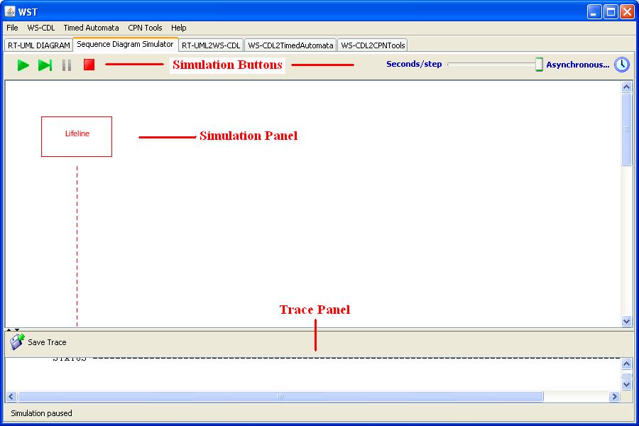
Figure 1. Sequence Diagram Simulator
In this tab the following parts can be distinguished:
-
The Simulation Buttons allowing the user to control the execution of the simulation (Run, Run Step, Pause and Restart) and the speed of the simulation (Seconds/step).
-
The Simulation Panel where the diagram simulated is shown. The different events ocurred in each one of the execution steps are shown by means of different colours.
-
The Trace Panel where the execution trace corresponding to the current diagram simulation is shown textually. The Save Trace button on the top allows the user to specify the name and the place where this trace is saved in the operating system.
RT-UML2WS-CDL
The third tab, called "RT-UML2WS-CDL", allows the user to transform the XMI code corrresponding to a sequence diagram (generated in the previous tab) into a WS-CDL specification.
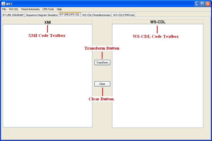
Figure 1. RT-UML2WS-CDL diagram
In this tab these parts can be distinguished:
-
The XMI Code Textbox where the XMI code to transform is shown. This code will be loaded automatically when the sequence diagram is exported to a XMI file in the first tab. Another way to load the XMI code is using the Open XMI File... option in the File menu. A dialog will be shown to the user to select the code to be opened. If the file opened isn't valid, an error message will be displayed on the screen.
-
The WS-CDL Code Textbox where the WS-CDL specification will be shown after doing the transformation. To save the specification, the user must choose the Save WS-CDL File... option in the WS-CDL menu. A dialog will be shown to the user to specify the name and the place where this specification is saved in the operating system.
-
The Transform Button allows the user to generate the WS-CDL specification corresponding the XMI code loaded in the XMI Textbox. The result will be automatically display in the WS-CDL Textbox after a few seconds. If the XMI Textbox is empty pressing the Transform button will have no effect.
-
The Clear Button allows the user to clean the content of both, the XMI Textbox and the WS-CDL Textbox. If both textboxes are empty pressing this button will have no effect.
WS-CDL2TimedAutomata
The fourth tab, called "WS-CDL2TimedAutomata", allows the user to transform the WS-CDL specification (generated in the previous tab) into a Timed Automata that can be opened by the UPPAAL tool. A diagram showing the different parts of this tab is shown in Figure 1.
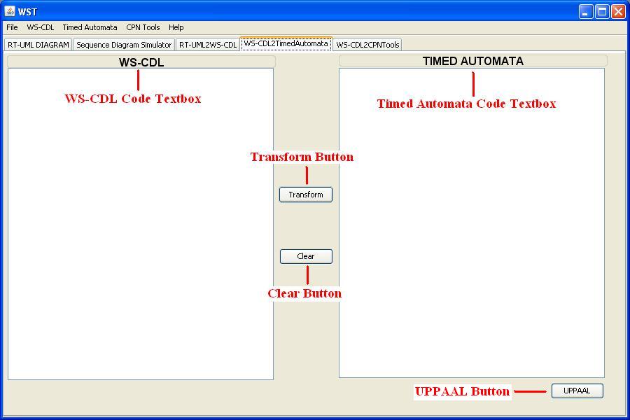
Figure 1. WS-CDL2TimedAutomata diagram
In this tab these parts can be distinguished:
-
The WS-CDL Code Textbox where the WS-CDL specification to transform is shown. This specification will be loaded automatically when the specification generated in the previous tab is saved. Another way to load the WS-CDL specification to transform is using the Open WS-CDL File... option in the File menu. A dialog will be shown to the user to select the specification to be opened. If the file opened isn't valid, an error message will be displayed on the screen.
-
The Timed Automata Code Textbox where the XML specification of the timed automata generated will be shown after doing the transformation. To save the specification, the user must choose the Save Timed Automata File... option in the Timed Automata menu. A dialog will be shown to the user to specify the name and the place where this automata is saved in the operating system.
-
The Transform Button allows the user to generate the Timed Automata corresponding the WS-CDL specification loaded in the WS-CDL Textbox. The result will be automatically display in the Timed Automata Textbox after a few seconds. If the WS-CDL Textbox is empty pressing the Transform button will have no effect.
-
The Clear Button allows the user to clean the content of both, the WS-CDL Textbox and the Timed Automata Textbox. If both textboxes are empty pressing this button will have no effect.
-
The UPPAAL Button allows the user to directly open the Timed Automata generated in this tab with the UPPAAL tool. To do that, it is necessary to save the Timed Automata generated before. Otherwise a information message will be displayed asking the user to save the automata before it could be openened by the UPPAAL tool.
WS-CDL2CPNTools
The fifth tab, called "WS-CDL2CPNTools", allows the user to transform the WS-CDL specification into a Petri Net that can be opened by the CPNTools. A diagram showing the different parts of this tab is shown in Figure 1.
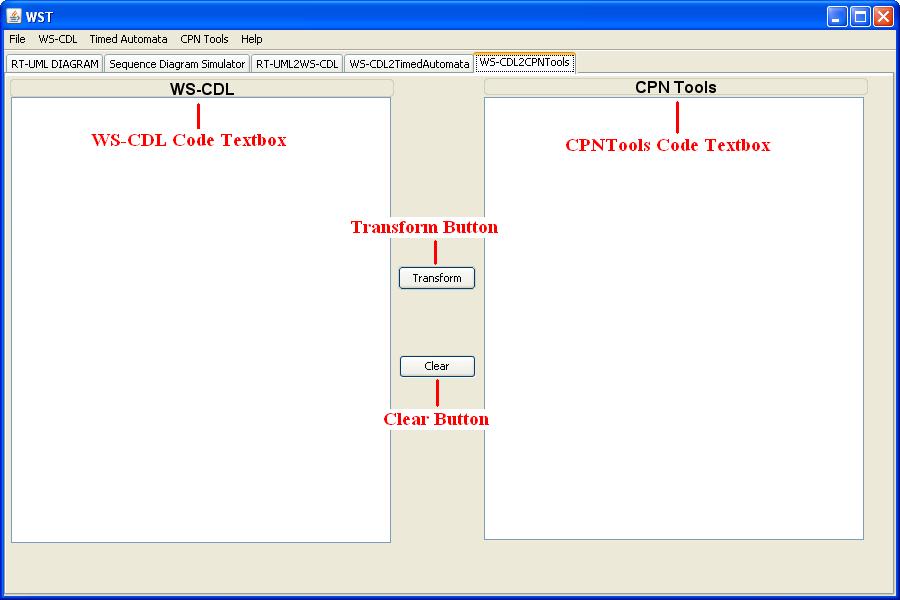
Figure 1. WS-CDL2CPNTools diagram
In this tab these parts can be distinguished:
-
The WS-CDL Code Textbox where the WS-CDL specification to transform is shown. This specification will be loaded is using the Open WS-CDL File... option in the File menu. A dialog will be shown to the user to select the specification to be opened. If the file opened isn't valid, an error message will be displayed on the screen.
-
The CPNTools Code Textbox where the XML specification of the Petri Net generated will be shown after doing the transformation. To save the specification, the user must choose the Save Coloured Petri Net File... option in the CPN Tools menu. A dialog will be shown to the user to specify the name and the place where this Petri Net is saved in the operating system.
-
The Transform Button allows the user to generate the Petri Net corresponding the WS-CDL specification loaded in the WS-CDL Textbox. The result will be automatically displayed in the CPN Tools Textbox after a few seconds. If the WS-CDL Textbox is empty pressing the Transform button will have no effect.
-
The Clear Button allows the user to clean the content of both, the WS-CDL Textbox and the Petri Net Textbox. If both textboxes are empty pressing this button will have no effect.
Example: An Aero-electric Management System (AMS)
The system consists of three parts: wind turbine management system, productivity management system, and demand management system. The productivity management system receives reports from the turbine management system and the demand management system, it then analyzes these reports and decides how many turbines should be working. The demand management system controls the power requirements for the area drawing up a report, which it sends to the productivity management system. To illustrate the translation we focus our attention on one event in the system, namely, sharp increase in power demand. The demand management system periodically checks the need to increase the production of electric power. In all, the increase of demand must be attended to within 3 minutes. The demand management system calculates how much power is necessary, and sends a message to the productivity management system to increase the production. Then the productivity system analyzes the need, sending a message to the turbine system to request how many turbines are available to turn on. The turbine system get the number of idle turbines. Then it sends a reply to the productivity system with the number of available turbines and when the answer is received the system decides if it is possible to satisfy the demand. If there are enough turbines it sends a message to the turbine system for them to be turned on or else it sends a message to the demand system to indicate that it is not possible to satisfy the new demand. Figure 1 shows the sequence diagram that we have created for this event.
/Diagram.jpg)
Figure 1. UML sequence diagram (XML File)
we can automatically obtain the WS-CDL code from a UML 2.0 sequence diagram, thus with this tool the generation of WS-CDL documents becomes immediate from the XMI code that we generate from the UML diagrams (Fig. 2). But we can also generate the timed automata corresponding to the WS-CDL code (Fig. 3). The obtained timed automata (Fig. 4) can be read and simulated by the UPPAAL tool, and we can also check some properties of interest with the UPPAAL verifier.
/WS-CDL.jpg)
Figure 2. From XMI (XML File) to WS-CDL
/TA.jpg)
Figure 3. From WS-CDL (XML File) to TA
/UPPAAL.jpg)
Figure 4. Timed Automaton (XML File)
The properties to check for this example are the following:
• The system must thrown an exception if the number of available turbines is not recieve before 3 minutes. This property is formalized as follows:
(System.Init_Interaction2_AvailableTurbines_interaction and x>3) --> System.Exception
We obtain that this formula is satisfied.
• The Productivity management system must always send the message Impossible_interaction to the demand management system when the number of turbines available is less than the number of turbines requested. This property is formalized as follows:
A[] System.Init_Interaction5_Impossible_interaction imply n_available < n_request
We obtain that this formula is satisfied.
• The Productivity management system must always order the wind turbine management system to turn on the available turbines when the number of turbines available is greater or equal than the number of turbines requested. This property is formalized as follows:
A[] System.Init_Interaction3_TurbinesOn_interaction imply n_available >= n_request
We obtain that this formula is satisfied.
In this example all the properties tested has been satisfied, so we do not have to modify our model. If we had obtained a negative result in at least one of the test, we would have had to go back to the UML sequence diagram and check our model to correct the cause of the problem. After that, we would have repeated the translation and the verification of the properties of interest.
Example: A Form Generator Service (FGS)
Web Services are being developed for multiple purposes, to create blogs, to do searches, to purchase goods, to process data, to manage information or to create new Web contents. In the last category we can include the Form Generator Service. The aim of this service is to allow developers to manage a form repository. The service provides interfaces for creating new forms, deleting old forms, modifying existing forms, and recovering previously created forms. Developers can thus easily reuse a form when they are developing a Web site.
In this case study we focus our attention on the function of creating new forms in the repository. Figure 1 shows the sequence diagram that we have created for this function with the WST UML-editor. In this diagram we can distinguish three different parties interacting:
• The User is the developer who wants to create a new form in the repository. He has to send the name of this new form to the FormService and, after that, all the information about the fields that compose the form.
• The FormService is theWeb Service that manages the creation of the new form. It plays the role of the intermediary between the User and the DatabaseService, making the requests to the DatabaseService and sending the responses to the User.
• The DatabaseService is the service that controls the access and modifications over the database where the information about the forms is stored. It guarantees the consistency and integrity of the database.
/Diagram.jpg)
Figure 1. UML sequence diagram (XML File)
In the process of creating a new form we can distinguish two different phases:
1. The User has to choose a name for his new form. A request with this name is made to the database. If the name already exists a new name has to be chosen. Otherwise, the name of the form is stored in the database.
2. The User has to send all the information about the fields that compose the new form. If the DatabaseService spends more than 2 minutes before sending a response to the FormService a Exception (time-out) occurs. Otherwise, an acknowledgement of the form creation is sent to the User.
Once the system has been modelled as a sequence diagram, it is exported to an XMI document. After that, the model is transformed into a WS-CDL specification by pressing the Transform button on the RT-UML2WS-CDL tab of the tool. Figure 2 depicts the XMI for this case study and the corresponding WS-CDL document.
/WS-CDL.jpg)
Figure 2. From XMI (XML File) to WS-CDL
After obtaining the WS-CDL document, we can move to the WS-CDL2TimedAutomata tab to perform the final transformation into Timed Automata. Figure 3 shows this conversion, from the WS-CDL specification to the resulting XML document with the Timed Automata specification.
/TA.jpg)
Figure 3. From WS-CDL (XML File) to TA
At this point, we have obtained a Timed Automata representation that can be open with the UPPAAL tool (Fig.4). When we open the resulting Timed Automata in the UPPAAL tool, we can perform a simulation of some possible behaviours of the system or we can verify some properties with the aim of proving that we have a sound system.
/UPPAAL.jpg)
Figure 4. Timed Automaton (XML File)
In this case, the properties that we intend to verify are the following:
1. We want to see if it is possible to reach the state where the form creation has finished successfully. The formula to check this property in UPPAAL is the first one in Figure 5. After pressing the checking button, we obtain that this formula is satisfied.
2. We want to see if when a timeout error occurs, the value of the clock controlling the waiting time is really greater than or equal to 2 minutes. The formula to check this property is the second one in Figure 5. In this case, the verifier shows again that the formula is satisfied.
3. We want to prove that when the system reaches the state that begins the creation of the form fields, the value of the boolean variable controlling if the name of the form already exists is false. The formula to check this property is the third one in Figure 5. Again, the verifier shows that this formula is satisfied.
4. We want to see if after waiting time greater than or equal to 2 minutes, the system ask the user to send the form information again. The formula for this property is the fourth one in Figure 5. In this case, the verifier shows that the formula is not satisfied. At this point, we should go back to our design and modify it. After that, we would repeat the translation process and we would try to verify the properties again.
/Queries.jpg)
Figure 5. Properties verified with UPPAAL
Example: An Internet Purchase Process (IPP)
In this example we show the use of the WST tool within a methodology to generate correct Web Service compositions.
Through the Internet, we can see a wide variety of Web Services where time restrictions play crucial roles. Perhaps, the most common of them and with which we must deal almost every day can be the “deadlines”. Clear examples are the maximum delay between two actions. For instance, we can think about the delay between the reservation and booking in a purchase context, or the delay between the abstract submission and the paper submission in a conference management system.
Traditionally, this kind of time restriction has not been tested until the system has been implemented. Therefore, any error in the design is propagated to the implementation, and the cost of detecting and correcting these errors increases, as we must return to the design phase. This can be avoided by analysing and verifying the design previously to the deployment into code. The WST tool can be a very helpful tool in this process.
As an example, we consider a typical purchase process that uses the Internet as a business context for a transaction. There are three actors involved in this example: a client, a supplier and a deliverer. The Internet purchase works as follows: “A client wants to buy a product by using the Internet. There are several suppliers that offer different products on Internet Servers based on Web-pages. The customer contacts a supplier in order to buy the desired product. The supplier confirms the order and contacts with a deliverer,who transports the product to the customer.”
The behaviour of each participant is the following:
• Client: He contacts the supplier to buy a product. He must send the supplier the information about the product and the payment data. After the payment, he waits to receive the product from a deliverer within the agreed time (48 hours). If he does not received the product in the agreed time, the payment is refunded.
• Supplier: He receives the client order and the payment information. The supplier sends an acknowledgement to the client, unless he is out of stock, and contacts a deliverer to transport the product.
• Deliverer: He picks up the order and the client information in order to deliver the product.
Analysis phase
In this phase we must identify the crucial requirements for the Internet Purchase Process that we have described above. For this process we have identified two different kinds of requirements. One kind refers to the proper behaviour of the system, while the other refers to the quality of the offered service. The proper behaviour of the system includes the fulfilment of timed restrictions and the correct processing of the payment result. The service quality is refined by two different requirements: the celerity of the service and the efficient request processing.
Figure 1 depicts the KAOS goal-model that we have developed for this example. The root goal “CorrectInternetPurchaseProcess” is decomposed into two subgoals by an And-refinement, which means that each subgoal must be fulfilled in order to achieve the root goal.
/GoalModel.jpg)
Figure 1. The goal model
The first one, “BehavesProperly”, which is of type “maintain”, is refined by another And-refinement on two leaf goals: The first leaf goal, “PickupOnTime”, is of type “Unbound Respond” and represents the aim that the deliverer must pick up the order on time, while the second leaf goal, “CorrectPaymentProcess”, is of type “maintain” and specifies that the delivery process will never happen if the payment is not valid.
The second one, “SatisfiedClient”, which is of type “PossibleAlways”, consists of three leaf goals that refine the parent goal by an And-refinement: The leaf goal “RapidService”, which is of type “Achieve”, determines that the client will receive the order on time, i.e., before 48 hours after the payment. The leaf goal “CorrectRequestService”, of type “Unbound Respond”, indicates that the product request will only be initiated if the product is not out of stock. Finally, the leaf goal “TryAgain”, of type “Unbound Respond”, indicates that the client must be able to repeat the purchace process if the payment is not correct.
Design phase
In this phase we model the behaviour of the system described before by means of a sequence diagram, taking into account all the requirements we have identified in the analysis phase. After that, for the next phase, we translate it into a network of timed automata.
Figure 2 depicts the UML sequence diagram corresponding to the purchase process, created with the WST tool. In this snapshot we can see the three actors involved in this system, and below two frames of type "alt". The first one is modelling the possibility of sending a correct or an incorrect payment information. The second one is modelling a choice between two options. It corresponds to an external choice depending on the value of the boolean variable “ValidPayment”. There is also a time constraint associated with the “SendProduct” interaction, whose meaning is that the delivery time cannot be greater than 48 hours. Otherwise, an exception is thrown, refunding the payment to the client.
We can also see at the end of the diagram two frames of type “exception”. The first one sends a notification to the Client when the Supplier is out of stock. The last one specifies that the payment is refunded if Deliverer does not send the product within the estipulated time.
/Diagram.jpg)
Figure 2. UML sequence diagram (XML File)
By using the second tab of the WST tool we can automatically generate the corresponding WS-CDL code (Fig. 3) and, in turn, from the WS-CDL code we can use the third tab in order to generate the corresponding XML-UPPAAL file (Fig. 4), whose associated TA is shown in Fig. 5.
/WS-CDL.jpg)
Figure 3. From XMI (XML File) to WS-CDL
/TA.jpg)
Figure 4. From WS-CDL (XML File) to TA
/UPPAAL.jpg)
Figure 5. Timed Automaton (XML File)
Finally, these timed automata can be read by using the UPPAAL tool, so that we can make simulations of the Web Service system and we can also check some properties on it.
Validation and Verification phase
Validation is made by means of simulation, where we check the system behaves as expected in normal conditions. For that purpose we use the UPPAAL simulator. This simulator can be used in three different ways:
• The system can be run manually, selecting the user which transitions to take.
• The system can run on its own, selecting the transitions to take randomly.
• The user can run a trace extracted from the verifier to see how certain states of the system are reachable.
After validation, verification starts, in which we verify some properties over the automaton we have generated. For that purpose we use the UPPAAL verifier. The properties we check with this verifier correspond to the leaf goals of the KAOS goal-model we have developed in the analysis phase.
• The first leaf goal, “PickupOnTime”, represents the situation that the deliverer must pick up the order on time, i.e., it cannot take more than 48 hours after receiving the request or an exception will be thrown. This property is formalised as follows:
(System.Init_Interaction6_SendProduct_interaction and Hour > 48) --> System.Init_Interaction9_RefundPayment_interaction
We obtain that this formula is satisfied.
•The second leaf goal, “CorrectPaymentProcess”, sspecifies that the product will not be delivered if the payment information is not valid. This property is formalised as follows:
A[] ValidPayment==false imply not System.Init_Interaction5_RequestProduct_interaction
We obtain that this formula is satisfied.
•The third leaf goal, “RapidService”, determines that the client will receive the order on time. This property is specified as follows:
E<> (System.End_Interaction6_SendProduct_interaction and Hour < 48)
We obtain that this formula is satisfied.
• The fourth leaf goal, “CorrectRequestService”, specifies that the purchase process will only be initiated if the product is not out of stock. This property is specified as follows:
System.End_Interaction8_OutOfStock_interaction --> not System.Init_Interaction1_SendInfo_interaction
We obtain that this formula is satisfied.
•The last leaf goal, “TryAgain”, indicates that the client must be able to repeat the purchace process if the payment is not correct. This property is formalised as follows:
System.End_Interaction7_PaymentNoOk_interaction --> System.Init_Interaction1_SendInfo_interaction
We obtain that this formula is not satisfied.
At this point we have found an error in our design, so we would have to go back to our diagram and fix the problem. In this example, the error could be easily solved by adding a frame of type “loop” wrapping all the payment process, in order that the process would be repeated until it finishes correctly. After this modification, we would perform the translation into timed automata again and the validation and verification phases.
Example: Registered Voters Management (RVM)
The use of Web Services for e-government has become more and more important in the last years. The expression e-government (from electronic government) refers to the use of Internet technology for providing services and exchanging information related to the government administration. The Service Oriented Computing paradigm provides an ideal framework for this kind of interactions.
In this case study we present a Service Oriented System that manages the lists of registered voters in a country. We distinguish two different kinds of lists: the federal lists and the local lists, for general and local elections, respectively. The following restrictions must be taken into account:
- A European Union citizen (but not a Spanish citizen) living in Spain could vote in the local elections of his city, but cannot vote in the general elections.
- A Spanish citizen who is living abroad could only vote in the general elections.
We focus on the case of a citizen who decides to register in these lists. In Figure 1 we show the different parts of our system: the citizen who interacts with the administration, the registry application that allows citizens to access the e-government procedures, the shared repository that contains all the information about the citizens and the communication protocols, and the multiple services for the different federal and local administrations.
/Schema.jpg)
Figure 1. Schema of the system
Figure 2 shows the sequence diagram for this case. When a citizen decides to register in the lists of voters, he has first to login in the system through the registry application. For the sake of simplicity, we are supposing that the login information sent by the user is always valid. After login, the registry application sends the login information to the shared repository, which has to be sent within a space of 5 minutes at most. Later, all the information about the citizen is extracted from the database of the shared repository, as well as the procedures that the citizen could use. This information and these procedures are sent in parallel to the registry application. Afterwards, the system shows the citizen the possibility of inscribing himself in any possible list of voters, depending on the circumstances listed before.
/Diagram.jpg)
Figure 2. UML sequence diagram (XML File)
Figure 3 depicts the XMI for this case study and the corresponding WS-CDL document and Figure 4 shows the conversion from the WS-CDL specification to an XML document with the Timed Automata specification.
/WS-CDL.jpg)
Figure 3. From XMI (XML File) to WS-CDL
/TA.jpg)
Figure 4. From WS-CDL (XML File) to TA
Figure 5 shows the resulting timed automata open with the UPPAAL tool. In this example we can distinguish two automata here: the main automaton "System" corresponding to the whole choreography and the automaton "Par_System0" that is used to implement the parallel interaction.
/UPPAAL.jpg)
/UPPAAL2.jpg)
Figure 5. Timed Automata (XML File)
Once we have obtained the timed automata, we use the UPPAAL tool to check the properties of interest in our system, which are the following:
• We want to see if the system reaches the exception location when a time-out occurs, i.e., when the citizen spends more than 5 minutes doing nothing after login correctly. The query is specified in the following way in UPPAAL:
(System.Init_Interaction3_RegisterVoter_interaction and x > 5) --> System.Exception
We obtain that this formula is satisfied.
• We want to prove that the registry application finally interacts with a local administration when the citizen is an European living in Spain. We assign code number 1 to an European citizen. Then, the query is specified as follows:
A[] System.Init_Interaction5_RegisterLocal_interaction imply CitizenType==1
We obtain that this formula is satisfied.
• We want to prove that the registry application finally interacts with a federal administration when the citizen is a Spanish living abroad. We assign a code number distinct to 1 to an European citizen. Then, the query is specified as follows:
A[] System.Init_Interaction6_RegisterFederal_interaction imply CitizenType!=1
We obtain that this formula is satisfied.
• We want to see if when an exception occurs during the execution of the parallel activity, both automata move to the exception location. In this case we have the following query:
A[] (var_parallel0==1) imply Par_System0.Exception and System.Exception
We obtain that this formula is also satisfied.
In this example all the properties tested has been satisfied, so we can consider our model as correct with respect to the properties of interest.
Example: An Aero-electric Management System (AMScpn)
The system consists of two parts: the wind turbine requester and the wind turbine provider. The provider receives a message from the requester with the number of turbines needed and, if it is a valid number, the provider tries to serve the resquest. If enough turbines are available, the provider delivers the turbines. Otherwise, the order is rejected by the provider and the system ends.
/img2.jpg)
Figure 1. From WS-CDL (XML File) to PetriNet
/PetriNet1.jpg)
Figure 2. Petri Net (XML File)
Example: An Airline Ticket Reservation System(ATRScpn)
In this example, we consider an airline ticket reservation system, which consists of three role types: Traveler, Travel Agent and Airline Reservation System. The system works as follows: the Airline Reservation System receives requests from travelers and travel agents to reserve seats, but travelers have greater priority, that is requests are served first in the event of a conflict. Thus, Airline Reservation System receives a trip request for a specific date and flight, and it must respond with the reserved seats.
/img2.jpg)
Figure 1. From WS-CDL (XML File) to PetriNet
/PetriNet2.jpg)
Figure 2. Petri Net (XML File)
Retics Group |
![]()
Related Links |
![]()